GitHub repository: andris
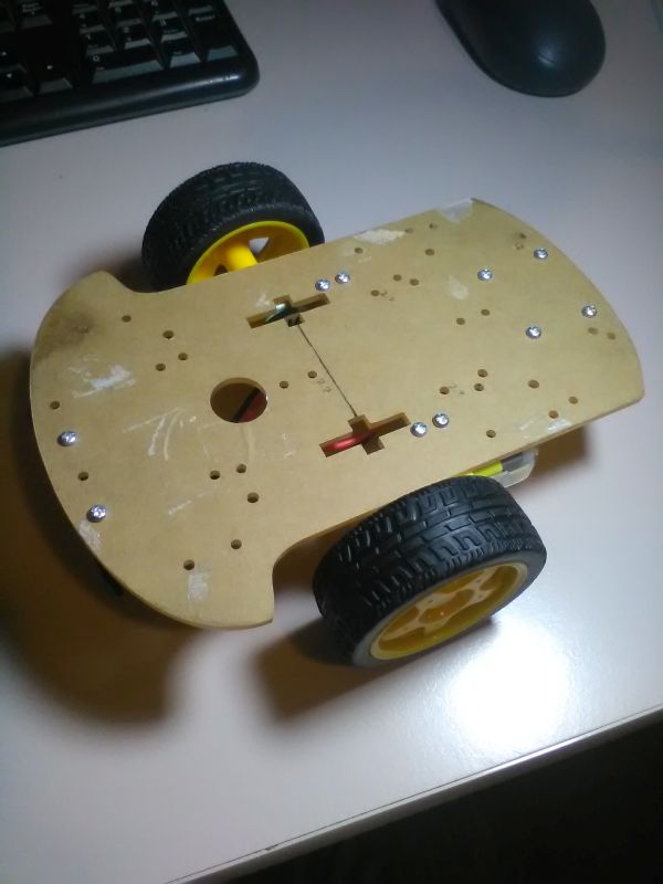
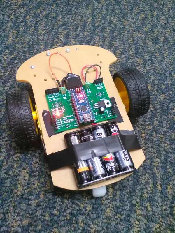
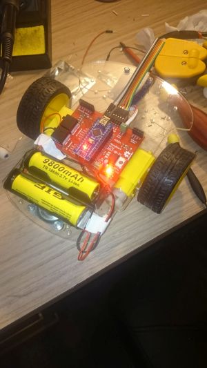
This project is to develop a robotics platform for educational purposes. It started as a project for a few friends and I, a long time ago. We bought some robotic chassis from eBay (pictured), and then mounted Arduino Nanos combined with a simple H-bridge motor controller (also from eBay) and a 4 x AA battery power pack to make a simple driving robot. We later added an ultrasonic transducer to help it detect walls. Then we got bogged down in the PID controller required to make it drive in a straight line (we used slotted optocouplers to measure wheel displacement using optical encoders mounted to the wheel shafts), and after a little bit too much messing around on GitHub, and one member leaving to pursue a degree at Cambridge (good on you!), the project kind of ended. We had also implemented serial Bluetooth control. So here it is, being picked back up.
There is some progress to document, but not too much. Most of the work we did was of use for prototyping and learning, but much of the knowledge has been internalised, and so I am no longer able to record the lessons learned. Instead, I will attempt to track decisions and learning since this point in time.
The first action taken was to open up the Git code, and see where we had got to. We then spent the next 3 hours trying to learn how to use Git from the command line. A bit of a waste of time, though we were nearly able to use it correctly in the end. This will need to be completed in the future, and workflows defined in order to be able to use it on current and future projects.
The next weekend, we met up and decided to work on hardware. By the end of the session, we had managed to get it moving around, controlled via Bluetooth. There were a few problems with loose wires, but we sorted them out. The other part of the work which was done was the beginning of the design of the motherboard PCB, which will be detailed more below within the context of the project.
First, the required components for the motherboard were noted:
Then, the schematic was drawn out according to the requirements. A few items were left out at first: the connector for the battery, the connector for the motor, and LEDs for RX, TX (on the serial connector) and a power LED.
Next actions:
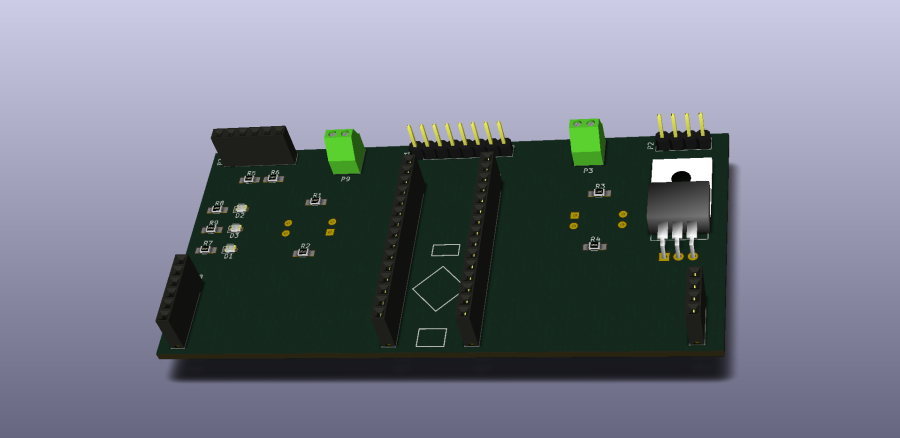
The schematic was fixed, and all the extra required parts were added. Footprints were matched to the schematic parts, and were created when they did not exist (i.e. for the optocoupler). The PCB layout was started, but no copper tracks have been laid. 3D models were associated with the parts. The physical dimensions of the robot chassis were mesured, and this was used to correctly position the parts on the PCB layout. 2x15 female headers were added to allow all GPIO to be accessed. The form factor was adjusted to save PCB space, thoguh it is largely limited by the position of the optocouplers and the size of the Arduino Nano. Though, could the Nano possibly be placed sideways? I just checked, and it is not possible or valuable to do so, since although assymetric placement will allow it, the presence of parts like the regulator and headers make it impractical. This possibility might be revisited in a future revision. The angled connection for the H-bridge connector was also updated.
Next actions:
I have measured a mounting hole on the centreline as 2.9 mm diameter and 5 mm vertically upward from the line directly between the two optocouplers. Since the optocouplers have a 2.54mm spacing, this puts the hole 2.54/2 + 5 mm above the ground pin of the left optocoupler. I need to draw all of this onto a diagram. It turned out to be too hard, so I gave up. I will print it all off at the end to check it. I added the other mounting holes in the same way, so now there are 3 points of contact. The PCB was revised V0.4.
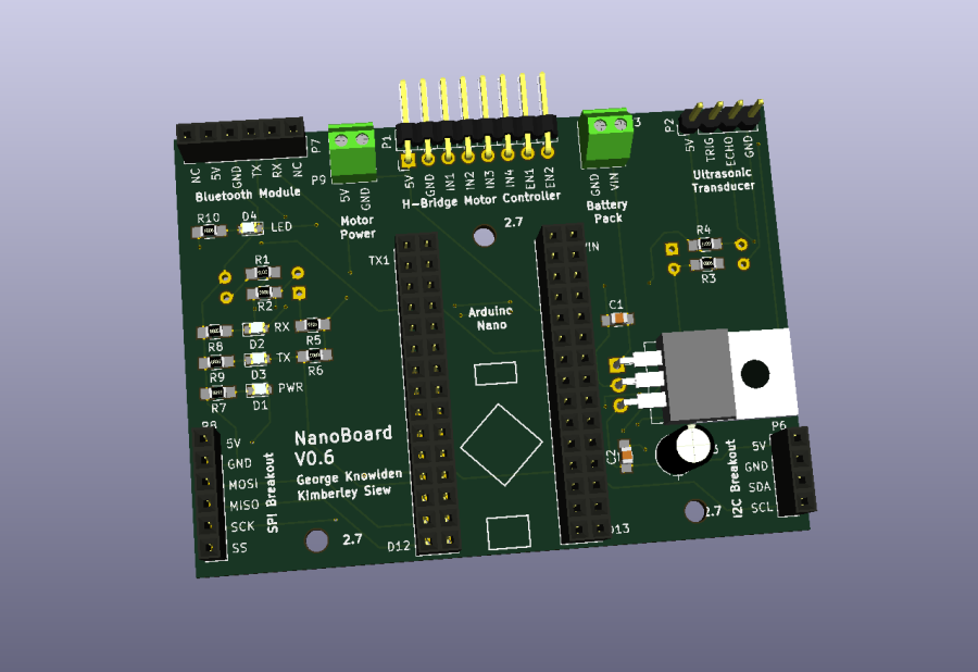
The indicator LEDs were labelled. I note than in a previous revision, capacitors were added to the regulator for voltage stablisation, and that a version stamp was finally applied to the board.
Labelled ports and pins:
Also made some more changes to board layout to allow the regulator to fit more easily.
Next actions:
Added an LED on pin A6. With the help of a collaborator, I adjusted the positions of the optocouplers and the mounting holes until they fit more accurately on the existing board. I routed the connections (which didn't take me as long as I expected). That only leaves me to adjust the width of the power traces slightly, and then export the gerber files for production.
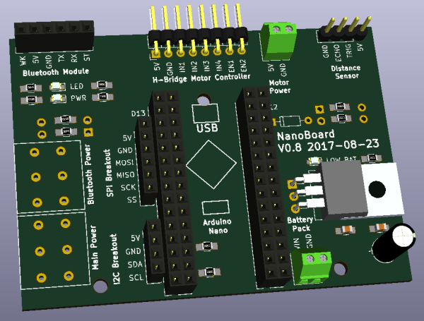
It's interesting to look at the PCB design as it developed:
Anoter job done today was a quick chat about using a centralised Git repository workflow. Our project is hosted here on Github already, so I put the workflow in the directory if anyone is interested. I won't post the link yet, since the relative positions of files will almost certainly change as this project develops.
Some future work also occured to me today: the H-bridge can, and probably should be integrated into the motherboard. This would potentially free up a lot of GPIO for customisation, and reduce the part count for the end user.
I decided in the end that adjusting the trace width was more trouble that it was worth. Instead, I put a capacitor over the motor pins. This could be sized a little higher, and now that I think about it, does very little for the design. I think I will remove it again. The next version will have to handle power traces better.
I think I'm just going to get it ordered, and make more changes later.
I plotted the Gerber files, and the drill file. Then I zipped them up, and made sure it looked OK on the dirtypcbs.com render. it did, so I ordered them! Let's see how many mistakes I made for $36.95 USD. DHL China should keep the shipping time down.
Next actions:
I exported a list of components for the board. The main parts required seem to be socket strips, as I think own everything else. Some money may be saved by using 1x15 female pin headers rather than 2x15, which is a decision that will be taken soon. I will source the parts through a combination of Element14 and RS.
An old error persisted on the dirtypcbs.com website: "Board outline not found in .GBR file". On the advice of these guys, I changed the edge.cuts layer to have a .gko file extension, and the new files were accepted without any problems.
The required parts were chosen, and were ordered for a total of $22.81 from RS. I also ordered a healthy number of spares to build up my library.
I realised there was another problem with the zip file: there were 2 .DRL files. I fixed this by combining them with GERBERV according to this post. Now, there are absolutely no errors and I really should be able to sit back and wait.
A friend points out that reference numbers aren't necessary on the silkscreen, and removeing them gives a cleaner look. He also mentions the advantages to having the KiCad files kept in Git, which makes open-source collaboration a possiblity.
Next actions:
Parts are still due to arrive, and the PCB has finished manufacturing and will begin shipping.
In the meantime, I thought I'd start a list of proposed changes, or things to implement, in the next version:
Next actions:
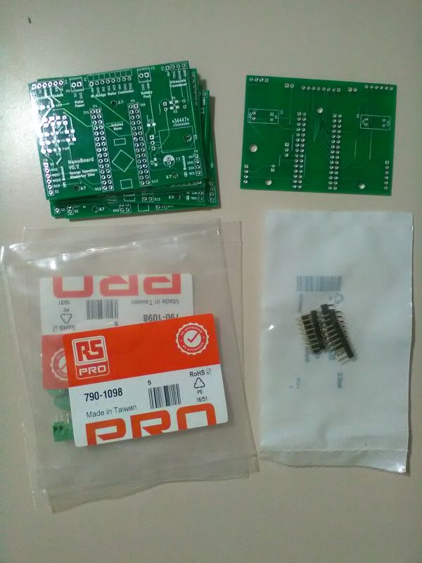
All the parts have now arrived from RS and DirtyPCB, including the screw terminals, the PCB itself, and the angled male headers:
My project partner and I practiced using the centralised workflow for Git, and we were successfully able to merge changes. This is a big step forward. The current KiCad model for the board was uploaded, the README was updated, and the file swere re-organised. The repository can be found at GitHub. This link was added to the top of the page for reference.
This weekend, the motherboard will be fabricated, and then tested. At this point, a brainstorm with my project partner will determine the next courses of action.
Next actions:
So, today our goal way to assemble and test the PCB/robot. Assembly was fine, no problems were encountered. One or two parts were re-soldered, but generally things were fine. Errors and improvement for the PCB were noted.
The errors found on the PCB are listed below:
Then we programmed some robot movement: success!
As you can see, now it makes sense to reconsider the problem of the PID wheel controllers. There was nothing straight about that movement.
Unfortunately we have some awkward clashes with different code libraries all using the timer interrupts and this meant we weren't able to compile the full code for testing. Specifically, we are having trouble with PinChangeInt and SoftwareSerial. In future, we are likely to have issues with the Servo library too. This is because they all use the same ISR vectors. There are a few options. I could use the hardware interrupts with the optocouplers, however, this would cause me to lose data any time I was running the ISR (which would take microseconds, but still, it would happen often). This is looking like my best bet. It would be nice to be able to use pin change interrupts freely though. Maybe I can solve the problem by reassigning the optocoupler outputs to the hardware interrupt pins, then use the bluetooth through the hardware serial, but disable RX and TX (between the Nano and the bluetooth module) while the USB is connected. This seems like a fair compromise. Or, i could do this, but instead of switching on the USB, switch with a physical switch. It would be nice if this was intuitive as possible though. Not sure which way to go with this.
After soome reading, SoftwareSerial is definitely out. So, now the choice is to either remove the BT module during programming, switch it's communication rails on and off, or have it automatically disabled when the USB is connected.
Actually, a friend suggested a better solution: resistors in series, causing the USB serial to override the HC-05 serial. As long as the signal integrity is preserved, this is a cheap and simple solution.
After a chat with my collaborators about licensing, we have unanimously decided to make it all open source. I have therefore licensed it under a Creative Commons Attribution 4.0 International License, to ensure that we don't run into issues down the track with Unlicense or WTFPL, as appealing as they are.
I also had a frank chat with my fellow contributors about the future and vision of the project. I envisage starting some kind of educational organisation for the teaching of robotics and embedded systems at schools. This robot would form a great platform for learning about robotics, and would be very useful as part of a syllabus for a university or similar. So, this robot should be developed with education in mind.
The project, and the repository were both renamed to something a little more unique. Andris was an automaticlly generated Greek name, and the acronym "AutoNonomous Driving Robotic Interactive System" was fitted retrospectively. It's the best we have for now.
Next actions:
I fixed some more errors, now we're down to the following:
The errors found on the PCB are listed below:
Still a fair bit of PCB work to do, and the key decisions involving the Bluetooth and the switch.
Next actions:
Increased the hole size for the optocouplers to 1 mm, with 1.7 mm for the pad (the same as a header pin setup).
Spotted another error: the 5V and GND rails on the battery connector are the wrong way around compared to the other connectors. these connectors need to have their positions rethought. A 3D model of the completed robot needs to be developed.
We hard wired the Bluetooth module to the hardware RX and TX pins on the Arduino. We had to unsolder the LED indicators to remove interference.
We tried various resistor values in series with the bluetooth RX and TX to find one that would correctly attentuate the signal from the Bluetooth so that it could be overriden by the USB serial. However, no suitable value could be found for the blueooth TX, so this element might require redesigning. The other possibility is to use MOSFETs to control the lines somehow. I'm not certain how this should be resolved.
The motor speed was determined to be an issue due to the different physical charactersistics of different motors (a reuslt of cheap eBay purchases). To compensate for this, we will redeisgn the robot to run off 2 3.7V Li-ion 18650 cells with a 6V regulator, designed according to this link. Then, we ordered a battery case, 4 18650 batteries and a battery charger for a total of around $16.
The name ANDRIS seems to be sticking for the moment.
Next actions:
It's been a little while since the last update. Progress today:
Next actions:
Worked on choosing a DPDT switch for the Blueooth serial/power. Found a sturdy-looking $1.09 SMD switch from RS Pro; it's a little large, but I think it will be OK.
I will need to design and include a low battery indicator now that we're dealing with Li-ion batteries. I might even need to include cut-off for low voltages, and also a charging circuit. Charging is not trivial, since the cells should be charged individually. I will leave this as a future problem, and will charge them with my dedicated circuit in the meantime.
Next actions:
Discovered another error: need to flip UT sensor so that it faces the right way. We also need to rotate the Nano so that the USB is accessible.
Now, all the schematic design is finished.
Going through the errors from before, everything seems to be resolved. Now just the hardware layout remains.
I worked on the PCB design until KiCad started crashing. A good cue to stop for the day. Lots of changes to layout so far, I'll do a comparison when I'm finished updating it.
I also added some python code to the Github repo to estimate velocity from some sample encoder data. Next step: tune Delta_t until it is appropriate for PID control.
This project is experiencing a bit of a revitalisation purely out of desire to own a robot that I had made myself.
Next actions:
I have read through the log, and created a list of the problems that need to be fixed, or checked:
As suggested on 2017-04-29, the schematic design seems mostly fine. I have, however, decided to put the motor back on to 5 V for the sake of sanity. I'm not convinced that the "adjustable voltage regulator" design was really working, and I was particularily concerned about dropout voltage. I also checked that the DPDT switches were wired correctly, which they were. The low battery indicator was implemented using a zener diode with a 5.1 V breakdown voltage, which should allow a ~2 V LED to switch off when the batteries are too low.
I've checked over the rest of the items, and everything seems fine. I'll do one last check tomorrow before wiring and then fabricating the PCB.
Next actions:
I finished wiring up the PCB. I probably should have checked it first... I looked back over the schematic, everything seems fine. I'm waiting for Kim to comment before I make an order to fabricate V0.10.
Next actions:
Kim raised a valid point: I can't just brush the motor voltage problems under the carpet. It turns out that the H-bridge controller board has its own 5 V regulator, and this explains why I've been running into problems (trying to run a 5 V regulator with a 6 V inbput voltage and a 2 V dropout voltage doesn't work on any level). Additionally, the Arduino has its own 5 V regulator. I don't think it's enough to run a servo on though, and for that reason I'll keep an external regulator. So, I need to put these changes through the schematic, and then update the board layout again.
So, that's done, and the PCB layout has been cleaned up a bit too. I sent the PCB off for fabriaction.
Next actions:
Also, for future reference, if this were to be a hobby kit of some kind, the components should be throughhole. This is more accessible for hobbyists and children alike. However, the BOM for this version still remains. I'm not going to bother doing an exact costing for this, especially at this early stage in the design, but with a $2.50 PCB, another $1 of passives and diodes, the connectors, the pin headers, the bluetooth, the batteries... it's looking to be around $20-30, not including the robot base. That probably brigs it up to around $50 total, ideally.
Next actions:
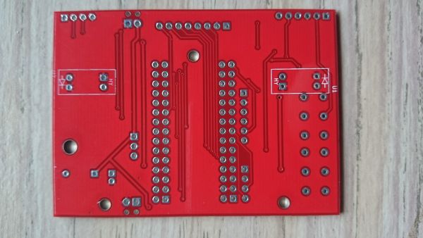
The boards arrived today:
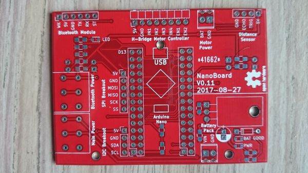
I'm soldering up the board at the moment, and I'm definitely regretting not doing thermal isolation on some of these pins, they are such a pain to warm up.
I finished soldering:
The zener diode seems to be doing it's job, which is great. And the switches work well. Here's the video showing that it's alive:
We're definitely going to need some proper software now...
Next actions:
I was doing some browsing, and stumbled upon the L293, which is the chip currently being used as a motor driver in ANRIS. In the next version of the breadboard, this should be included in a DIP package. I had better start a bit of a wish list:
Next actions:
I got some more code working on ANDRIS. I ended up updating the NanoDrive function to take two float arguments, one for each motor. So, for example, NanoDrive(1, -1) will rotate the robot clockwise on the spot, as fast as it will go. Then I updated the other movement functions to take duration arguments. The code looks a lot cleaner now.
Another problem has been spotted: the omnidirectional wheel I'm using sucks. I'll try to find a better one online: I just bought a new one on eBay.
Apprently the SN754400 is a better choice for a motor driver, since it dissipates less power.
Tomorrow I think I will spend some time cleaning up the libraries and making some unit tests. The debugging code and the functional code needs to be seperated, and redundant code needs to be archived. The left encoder MIGHT not be working, but the code is too much a of a mess to be able to easily tell.
Next actions:
I just spent the day trying to move the code into a class. However, I ran in to lots of problems when it came to integrating the Interrupt Service Routines (ISRs) into it, so I had to give up. As an afterthought, the functions tructure is probably more intuitive for a new coder anyway. What a monumental waste of time. At least I learnt a little about C++.
Next actions: