
This project is to design and build a farm robot for performing tasks around an Australian farm. It was inspired by this robot, the Summit XL 4WD Autonomous Robot, which was on sale for a mere $14450 USD. I had a funny feeling I could beat the price if I made my own, and once the ideas was planted in my head, there was no turning back.
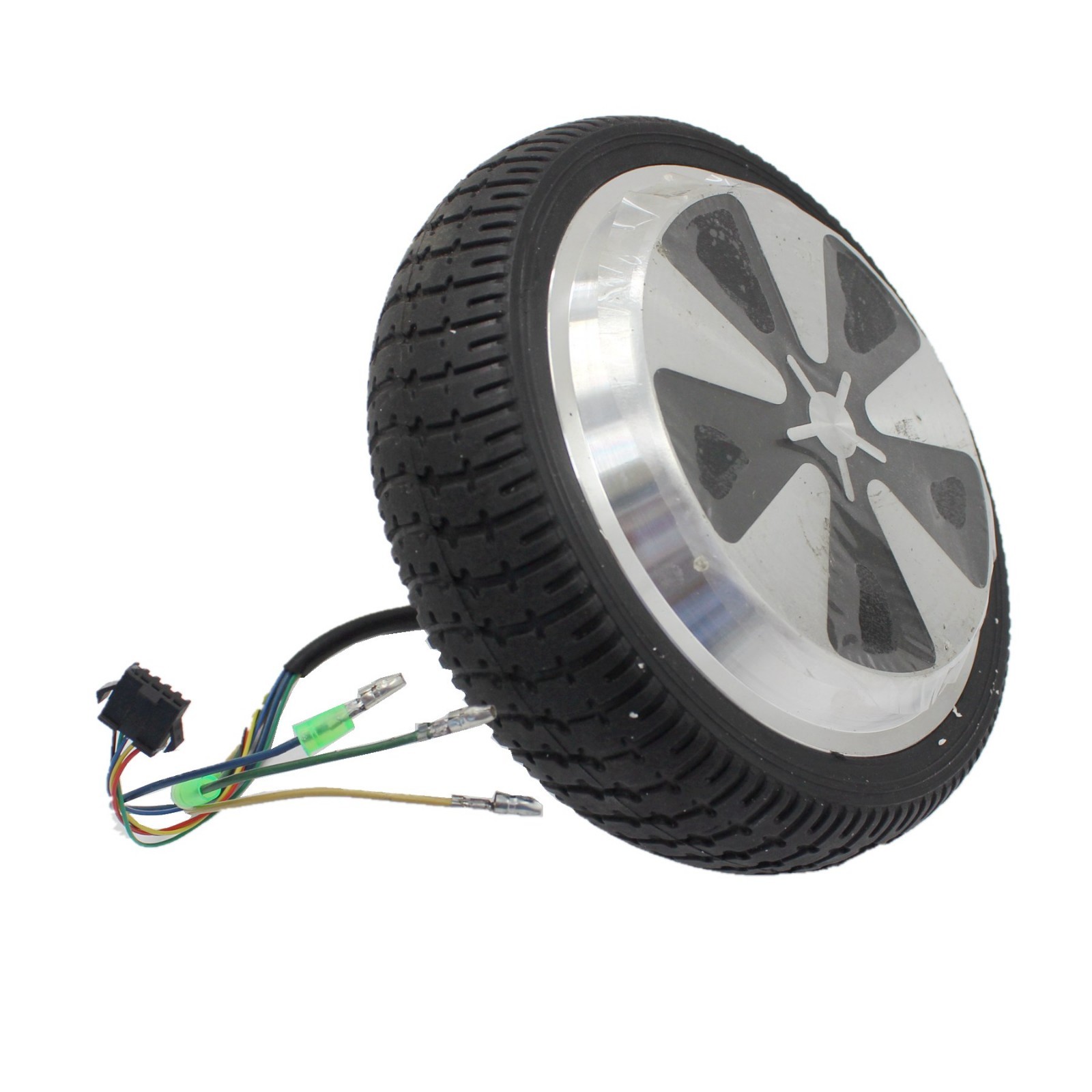
After watching this Youtube video, I decided to buy a 350 W DC motor from a hoverboard (pictured below) and the appropriate motor controller (search for "12 to 36 volt 500 watt brushless motor controller") for around $50 AUD. A good deal to see if things work! More details can be found here.
Next actions:
I've been doing a little bit of research into LiDAR technology. At university we used HOKUYO and SICK LiDAR units, but they were primarily for indoor use and were very expensive. I've been investigating low cost units for outdoor use. Some of the big standouts:
On the whole, I am most interested in the Sweep and the YDLIDAR X4. I'll probably buy the YDLIDAR first, since it is much cheaper. It would be great to do a comparison of the two prodcuts, and there seem to be plenty available from aliexpress.
The other interesting thought is that LiDAR will work better at night, so it might make sense to charge during the day and navigate at night. Also, for actual DBH tree measurements, the scanner will probably need to be mounted at 1.5 m, making it useless for robot obstacle avoidance. Maybe the rover will have two scanners, one for looking in front near ground level, and one for scanning tree trunks. An exciting prospect. Combined with a camera and IMU, this will form an impressive range of sensors.
Some great resources on ROS and the Neato LIDAR can be found here.
Next actions:
The motor arrived and I tested it. Unfortunately, the driver I have doesn't support the hall effect sensors, so I'm going to need to buy a second proper one to test that properly. The good news: it works! 12 V is plenty, seemingly.
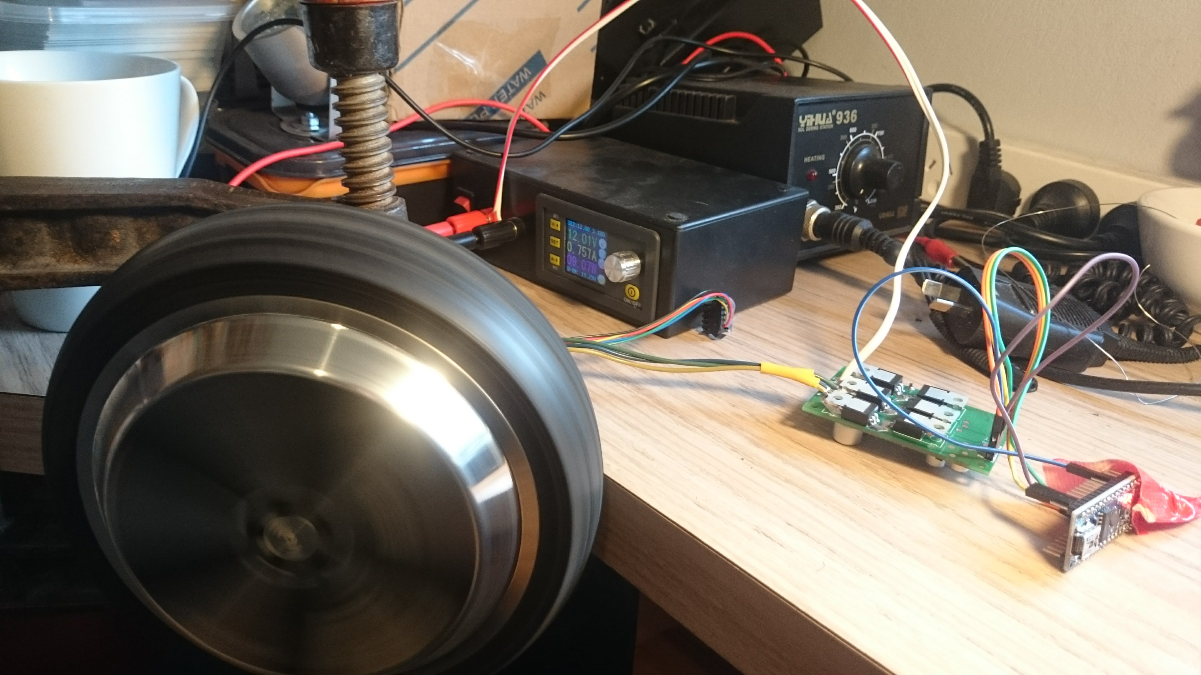
The no load test gives around 0.75 A at 12 V at full speed, ~9 W. At 30 W, the friction of the rubber on my hand begins to feel unformfortablly warm and mechanically painful. I don't think it will use much more than that on average. So, at 0.75 A per wheel, 4 wheels gives 3 A. A nice round number. One of my 17 Ah batteries would give maybe 4 hours of driving, 2 would give around 10 hours. This doesn't include power for other peripherals, but I think it's a good start. There's a possibility I'll boost convert the voltage to get higher torque, but more likely I'd just be looking for better motor efficiency. To properly do that I'm going to have to characterise the motor at different voltages, speeds, and torques. This is a lot of work. I'll just test this with the proper hall effect sensor setup and see if I can get a better stall happening (currently the motor changes direction and runs slowly). I could detect this condition by examining the output, but I would rather it didn't happen in the strange way that it does.
I'm thinking about controlling carious parts of the robot with Arduinos as an itermediary. I'm thinking that I might run out of GPIO on the Pi, but I'm also worried about latency. Something's telling me that latency won't be an issue. It's tempting to use the USB ports of the Pi to control various Arduinos, i.e. one for motors, one for LiDAR. I would eventually run out, but I can always add USB expansion. The main benefit is much cleaner wiring, but it also makes everything modular and easier to debug. Yeah, this is a good idea.
Practically, for batteries, I would probably use the more cost effective 7.2 Ah units. I'll work this out later.
So, current design:
Current BOM is looking to be around $400, without LiDAR. Important items to buy, in order:
Next actions:
The LiDAR arrived, and it worked perfectly!
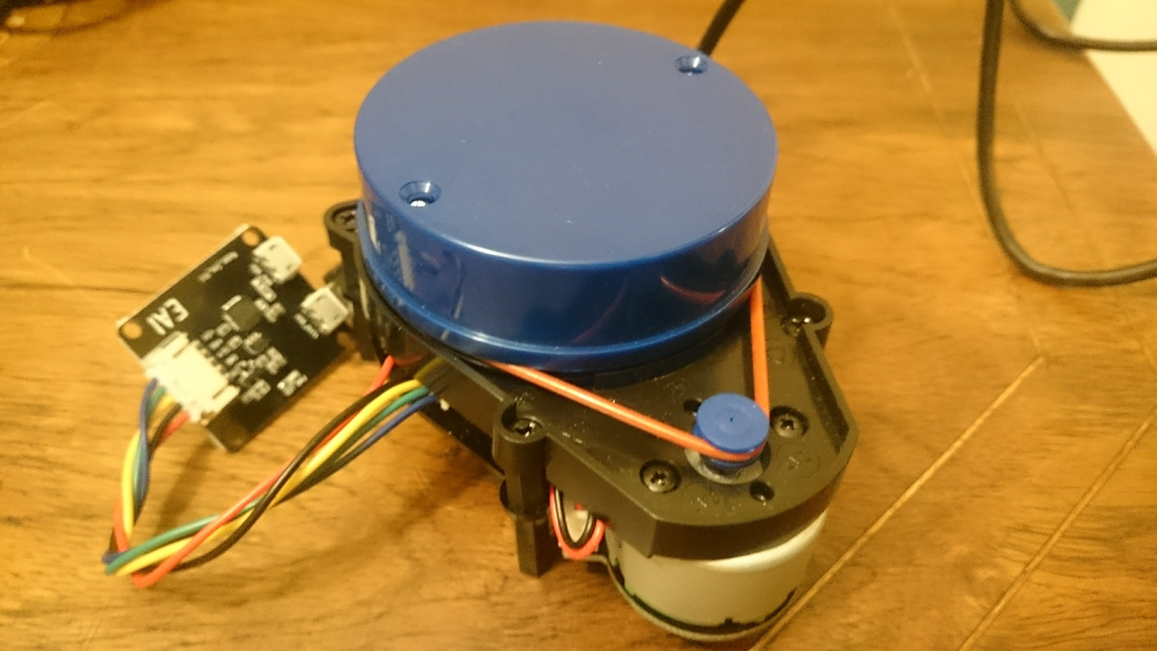
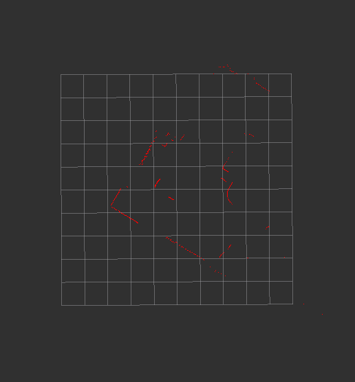
rviz in ROSFor anyone aspiring to get the YDLIAR X4 working, here are my instructions to you.
On Ubuntu 16.04:
ROS for Ubuntu 16.04:
$ sudo sh -c 'echo "deb http://packages.ros.org/ros/ubuntu $(lsb_release -sc) main" > /etc/apt/sources.list.d/ros-latest.list'

$ sudo apt-key adv --keyserver hkp://ha.pool.sks-keyservers.net:80 --recv-key 421C365BD9FF1F717815A3895523BAEEB01FA116

$ sudo apt-get update

$ sudo apt-get install ros-kinetic-desktop-full

$ sudo rosdep init

$ rosdep update

$ echo "source /opt/ros/kinetic/setup.bash" >> ~/.bashrc

$ source ~/.bashrc

$ sudo apt-get install python-rosinstall python-rosinstall-generator python-wstool build-essential
$ mkdir -p ~/ydlidar_ws/src

$ cd ~/ydlidar_ws/src

$ git clone https://github.com/EAIBOT/ydlidar.git

$ cd ..

$ sudo apt install catkin

$ catkin_make

$ echo "source ~/ydlidar_ws/devel/setup.bash" >> ~/.bashrc

$ source ~/.bashrc

$ cd ~/ydlidar_ws/src/ydlidar/startup

$ sudo chmod +x initenv.sh

$ sudo sh initenv.sh

$ sudo apt-get install python-serial ros-kinetic-serial g++ vim ros-kinetic-turtlebot-rviz-launchers
$ roslaunch ydlidar lidar_view.launchThere's actually a lot to learn about ROS, and I learned as much as I could today. The main points that I can remember so far, as far as they relate to this farm robot's design, are:
ros_arduino_bridge shows a lot of promise.ROS, but the best way is probably to read the wiki closely and learn through practice. By attempting to do more and more complex things, and keeping my own notes, I should be able to advance my knowledge to a useful level. Python will thankfully be sufficient.gmapping, hector_slam etc. are all viable, but one will be right for me. I don't have to worry about this for the moment, I can focus on taking one step at a time.ROS would be to connect a motor to an Arduino to a PC via Serial, and control the speed with my keyboard. Then I can move on to getting encoder data, and graphing it in realtime, and then controlling multiple motors, and then controlling it all remotely, and graphing remotely... Taking a step back, installing ROS on a Pi would be a good start. I've ordered one, and am waiting for it to arrive.There's also the physical design of the chassis to think about. I like the idea of aluminuim construction. This picture gives a good indication of how the motors are mounted, and I think I'll follow suit. The rest of the design should be pretty basic really. Things like the LiDAR and GPS will obviously have to be mounted above the robot, and they will be weather protected accordingly. I wonder if I'm going to have much trouble with transparent plastic over the dront of the LiDAR... no, according to the datasheet, the sensor uses 775 to 795 nm light, and according to the net, some acrylic/plexiglas tubing would do the trick. 95 mm ID tube seems fairly common. A shame I need 110 mm to fit the whole thing in, but maybe I can come up with an alternate mounting system.
Also worth bearning in mind: this is the YDLIDAR X4. The G4 is nearly 4 times the price, but is smaller, and has a 16 m range rather than a 10 m range, and roughly double the scan rate. Which reminds me, it might be worth trying to drop the scan rate in order to increase the range. I don't even know if this is possible or practical really.
So, let's establish the order of goals for the moment:
ROS on a Raspberry Pi 3 B+ROS on an Arduino controlling the driverNext actions:
ROS on a Raspberry Pi 3 B+Trying to install ROS on a Raspberry Pi 3 B+ according to these instructions. This was chosen over Ubuntu, since the Raspberry Pi won't be supported for a few more weeks probably. I'll learn how to do it with a few different methods, and record the results here. Actually, I've changed my mind again. I'm going to learn how to install it all myself. Raspbian first according to this set of instructions. Things look good so far. Compilation is going fine, even though I'm installing a Jessie version on a Stretch Raspbian. It installed!
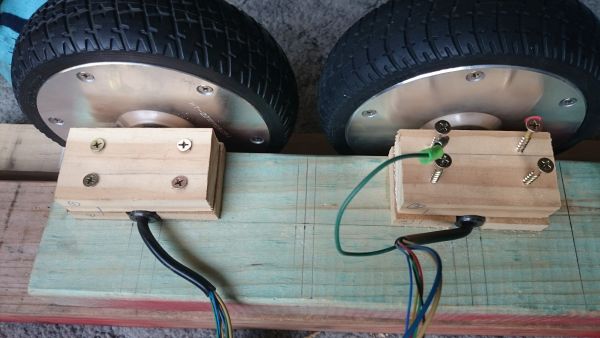
I had a few problems with finding the right sized headers for the motor driver. I'm just going to have to solder the wires on directly. Well, that works really well! The VR pin controls the speed, the enable pin needs a high enable, and the ZF pin controls direction. The signal pin gives some indication as to speed. This can be calibrated later.
So, I've completed both of my goals for the moment. My next step should be to get the YDLIDAR X4 working on the Pi. This wasn't easy, I have a feeling that I'm going to have problems with Raspbian. I need to swap to Ubuntu. Managed to install by carefully following the instructions here. It involved downloading and overwriting a bunch of files on the boot partition. Then I was able to boot, and with an ethernet internet connection, I was able to update and upgrade. Then I copied over the wifi drivers according to the same link. After installing wireless-tools, I could run iwconfig and see wlan0, but I couldn't get the WiFi working. I'm also having a weird problem every so often when the somcputer fails to shut down properly. The plug needs to be pulled to make certain.
Next actions:
ROS on a Raspberry Pi 3 B+roscore is running! So, now I need to install the YDLIDAR drivers. Done! As long as you run ydlidiar.launch, it works in headless without throwing errors. So, another target bites the dust. Now, although I can see the laser scan results remotely, it would be great to be able to actually view the map. I'm sure this will come later.
Next actions:
ROS on an Arduino controlling the driverAlright, Arduino control. I'm going to use this code to make it work, or an equivilent. This might be a bit limiting. I think I might wreite my own, just to be sure that it works properly. Now I'm trying with rosserial, which looks like it's improved a bit. I got that working by following the tutorials, with no issues. Now I can control the motor with a publish command, and subscribe the the encoder outputs! Life is good.
I'm not so interested in keyboard control for the moment, since I think the differential drive stuff will be more useful. But, to really use that, I need a second motor. So I think I'll buy one, with a controller, and leave this on hold for the moment. ros control looks like the best bet. I've ordered the new motor and driver.
Something else I thought of yesterday was the importance of braking. Without it, the drivers I have won't be able to stop, and they stall easily if you set the speed too low, and have to be reset by disabling and re-enabling them. It's a pretty annoying problem. I could try to reverse engineer the motor drivers, but I think I'm better off dealing with it in software. I could detect motor stalls at a variety of places in the code (Arduino, ros-control) and will get to it later. I found someone who had made a brake for this exact controller and motor here on Youtube.
So, next I need to hook up both the motors to an Arduino (I can use 1 interrupt fo each motor, and later I can use 1 Arduino for each set of sides). Then I need to work out how to use this package to control a differential drive robot. Until then, I need to get really good with ROS. So, I'm going to work through the suggested tutorials in order, from:
Next actions:
Lot's of reading about ROS. I went through the main tutorials again, and made it though all the non-simulated parts of the URDF stuff. I'm ready to try simulating Burt 1.0. I had some weird problems trying to load the models for gazebo, but I ended up downloading the files manually. I only needed the sun and the ground plane.
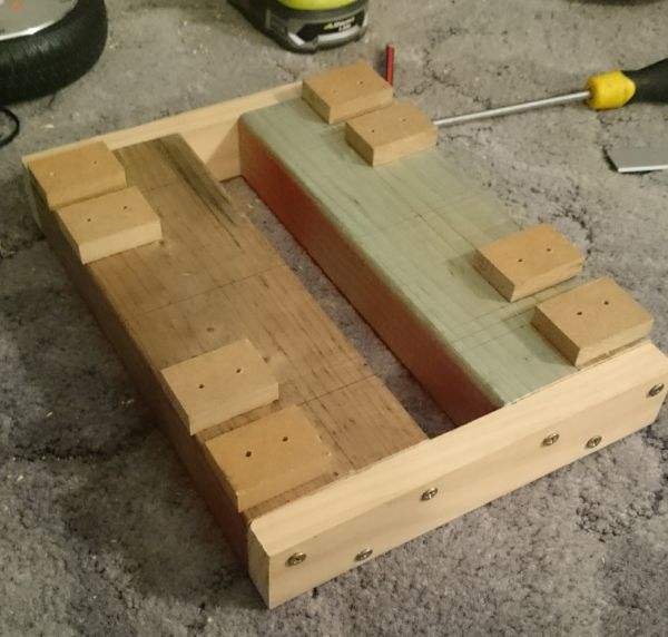
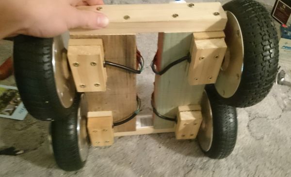
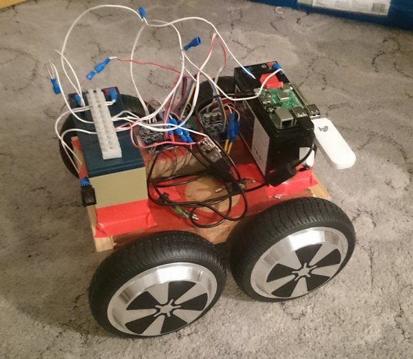
Lots of progress! I've put together the bulk of the chassis, using a pretty hacky method to secure the motors.
I also had a play with various joystick options. Although I was able to get the Xbox One controller working in wireless mode, I couldn't find it on bluetooth, so I've bought a cheap one on eBay with a USB reciever. I'm still waiting for the BLDC motor drivers to arrive, and I feel as though I need more hardware before I go further with software.
Next actions:
I did a lot of work yesterday. I got 2 motors connected to 1 Arduino, and then connected that up to ROS on my laptop. It worked well, but one of the drivers seems to be broken. I'll have to order another, just in case. Then I decided that the next step was wireless control, so I connected the Pi to the Telstra dongle that I have:
$ sudo apt install usb-modeswitch usb-modeswitch-data

$ ifconfig -a

$ lsusb

$ sudo usb_modeswitch -c 12d1 -p 1f01 -V 12d1 -P 14db -J

$ lsusb

$ ifconfig -a
Then edit /etc/network/interfaces:
#this first bit is in a different file under interfaces.d/

allow-hotplug eth0

iface eth0 inet dhcp


#this is for the dongle

allow-hotplug eth1

iface eth1 inet dhcp
Then, to get it going:
sudo ip route change default via 192.168.1.1 dev eth1
There's some more code somewhere to automatically configure the modem on the fly, but in the meantime this works fine. Sometimes running ifconfig seems to fix some things.
Then I installed zerotier from source, but have yet to create it as a service.
Next actions:
I got zerotier running as a service, but it took a little more care than usual to enable the service. No real notes on how to improve that. Then it got in a weird race condition with some other stuff, so I put a sleep 60 before a sudo systemctl restart zerotier-one.service in /etc/rc.local to make sure it works. It added a bit to boot time, but at least I know I can boot into a virtual network connected device in under 2 minutes. Some UI buttons/lights would help at this point. OK, time to get this mounted on the bot! Tomorrow maybe. And I just ordered the new motor driver.
Next actions:
I thought I'd have a go putting the Pi on the robot. There is a power supply problem, which I have tried to temporarily solve by keeping it topped up with my bench power supply, but this obviosuly won't do. I need a much better 12 to 5 V converter. Until then, I was able to use a better cable and get the power supply I needed. Meanwhile, following this link to install ROS. I switched to ethernet for the installation, I don't want to waste my mobile data. Speaking of which, I installed vnstat to keep tabs on my data usage. Time to start writing the recipe.
I think I might experiment with using the 5.1 V that the standard supplies use, rather than the 5 V that I think I'm actually giving it. I have some LM2596 modules lying around, I think I'll try using one of those instead, since they are apparently rated for 3 A (from datasheet). Slightly annoying not to have the female USB output... I bought some from China, and in the meantime I will improvise.
Next actions:
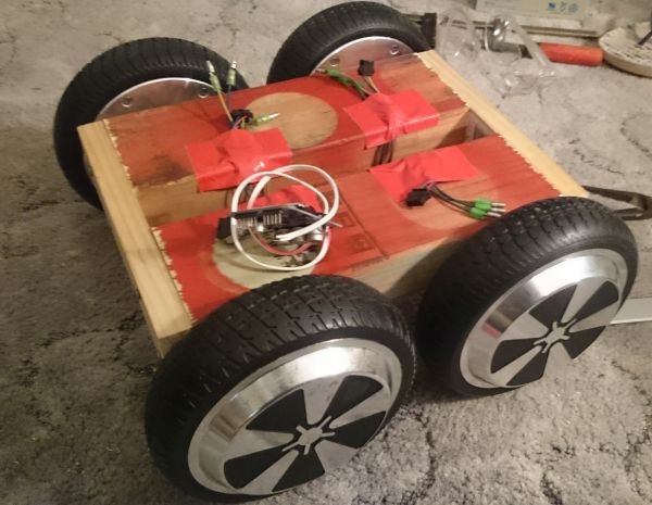
I used an adjustable LM2596, giving an OC voltage of around 5.5 V. To set it exactly, I used stress --cpu 4 and modified the converter to give around 5 V at the source. I also took it for a test drive (no video unfortunately). The basic results:
I think I'm going to install both drivers, even though one is broken, and limp around on 3 wheels for the time being. It will be better than the current state. Then I can start working on the differential drive. I can also make the IMU and GPS. There's nothing stopping me from witing up the LiDAR, but I feel I should keep that for a bit later, once everything is set up.
Having real troubles with the motor drivers at the moment...
Next actions:
Enough is enough. I'm making my own ESCs! After chatting to a friend with a lot of experience, we chose the VESC which is a great open source project. I installed KiCAD, and started looking over the schematic for the Mini VESC, which looks close to the mark. My friend made the observation that the drivers and current sensors could both be downgraded, and we'll see about the FETs themselves. Perhaps these?
Next actions:
ROSFound this link for MOSFET selection for BLDC motor drivers.
After several hours of browsing and learning, I've limited my selection to either the MAX9918, MAX9920, or the MAX4081. A full explanation of the choice can be found on Github (I've created a fork of the Mini VESC). Now I just need to select one of them and move on to the next stage: MOSFET and MOSFET drivers.
Next actions:
ROSI'm short listing the MAX9920, since it's cheap, has low gain, and good noise characteristics. Now I want to compare it to the AD8418 from the high end design that I'm looking to copy from. Given that the maximim current I'm expecting is around 20 A peak, and VSENSE is 200 mV, and VOUT should be from around -2.4 V to 2.4 V (bidirectional application), then gain must be 2.4/0.2 with is 12. The application notes also suggest that 20 A should give 200 mV, so R = 0.2/20 = 10 mOhm.
Slight adjustment: VDD = 3.3 V. So, using 3 V as the max range, it's actually -1.5 to 1.5. If we adjust IMAX to 25 A, and a gain of 15, then we're looking at (1.5/15)/25 Ohms = 4 mOhms for the current sense resistor. To set a gain of 15, setting R1 = 1 kOhm, then R2 = 59 kOhm (page 15 of datasheet).
Next actions:
ROSIt's $8.15 for a DRV8301, and $6.45 per IRF7749 (worst case DigiKey price), so that's $27.50. So, instead, I'll use the DRV8301, but then a much cheaper FET, maybe something like the IRFH3707 for $0.80, making the total price $10.55. And if I use the DRV8303, then I can drop the driver price to around $5.48, giving a system price of $7.88, which is a massive price decrease.
Current BOM:
Total: $32.82
Today, the wireless controller arrived. Running it was as simple as plugging it in, then running roscore, (new terminal), rosrun joy joy_node, and then echoing the results to the screen. Thanks very much to the "ShanWan PC/PS3/Android" with idVendor=2563, idProduct=0575 as reported by dmesg. I guess there are no excuses to avoid starting work on some differential control now. Following this guide, I was able to create a YAML file to publish /cmd_vel messages. Easy!
Next actions:
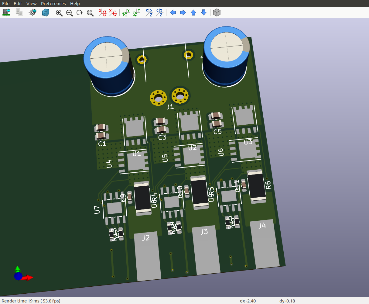
ROSI did a big day of work today, and finally finished the schematic and footprint selection. Since my last update, I have:
I've also started to think about heat-sinking. Currently, the plan is to have an aluminuim plate on the bottom of the board with a 0.5 mm thermally conductive layer set between it and the PCB ground plane, with stitched vias to the thermal pad of the FET, all bolted together.
Next actions:
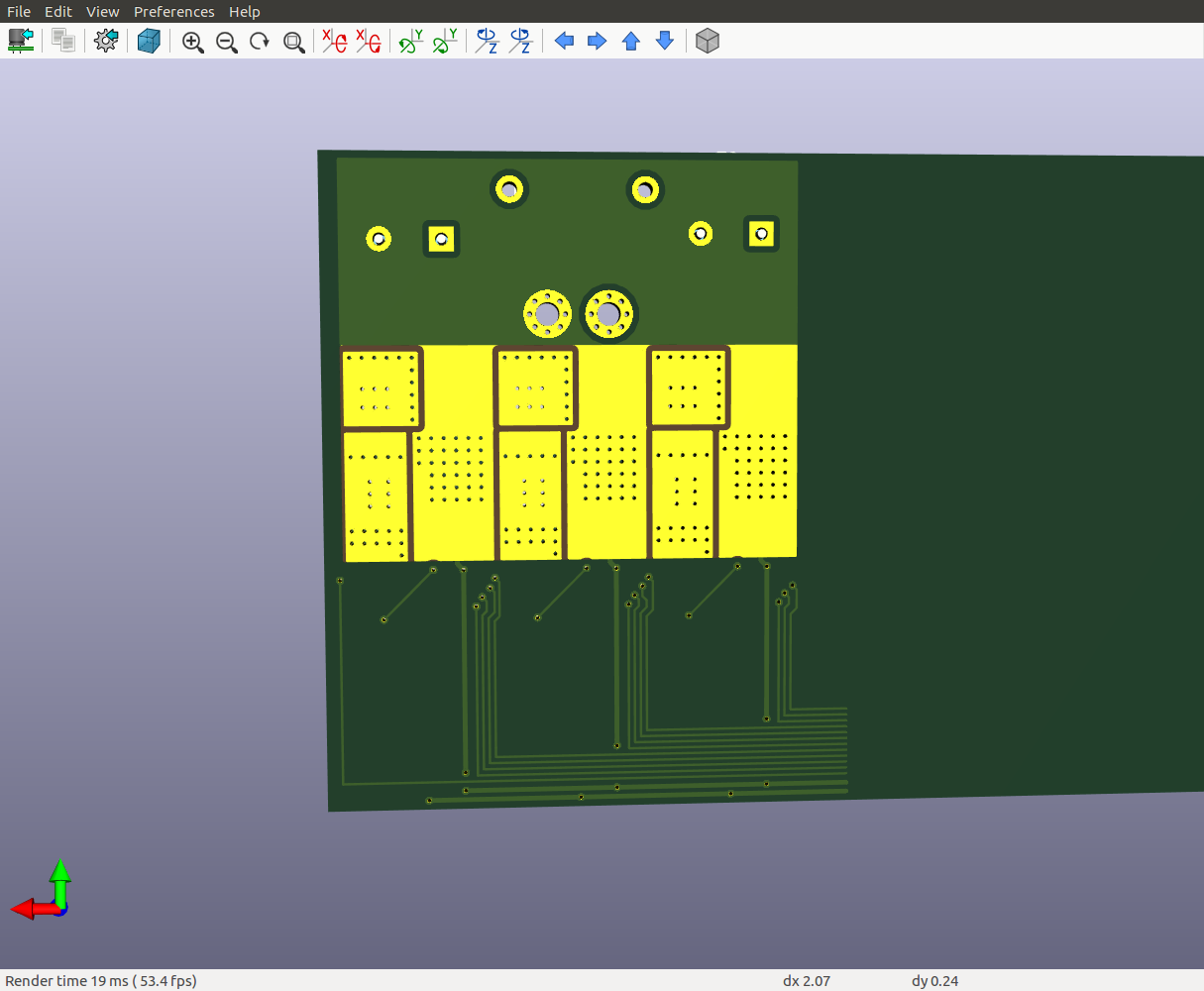
ROSTrying to pick up where I left off. Still working on the PCB design.
Next actions:
ROS