GitHub repository: tree-measurer
This project is to design and build a product capable of measuring the height of a tree with a reasonable degree of accuracy. It's currently quite difficult to estimate, and various methods found online have been unconvincing. Since there are around 250 000 trees on the tree plantation that my dad works on, the problem is worth throwing a little bit of effort into.
A fair amount of work as already been completed, so this will begin with some catch-up documentation:
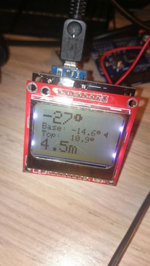
The device measures the tree by getting angles of elevation and depression to the top and bottom of the tree, and then given a 10 m distance from the base of the tree as measured along the constant gradient ground (assumption), given an average male height, it calculates the height of the tree. In the future I hope to include the distance and diamter reading of the tree in the same device, but this adds considerable cost to the project for a relatively small reward.
Next actions:
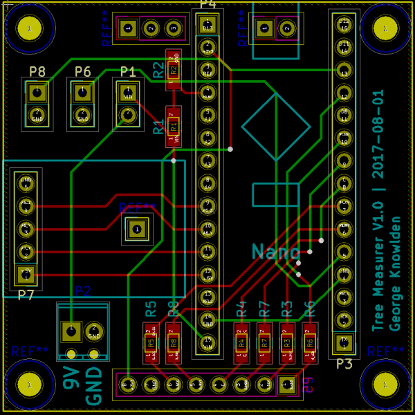
I added the GitHub link to the top of the page with the relevant gerber files and code. I also put the OSHW logo on the PCB.
Next actions:
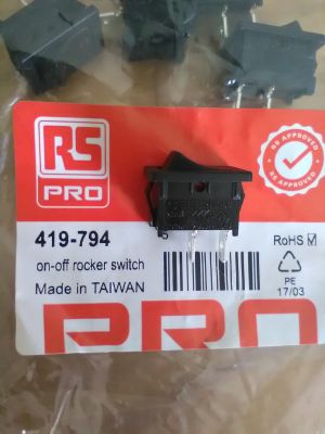
The rocker ON/OFF switches have arrived, looking pretty nice:
The newer eBay style Nokia screen and ADXL335 have both arrived to check for future compatability. The screen pinout is known to be different, and the ADXL335 must be checked.
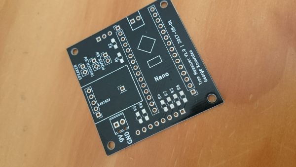
The PCBs have arrived, after 38 days. I probably won't bother with the 1-8 week shipping in the future, unless there really isn't a hurry.
Next actions:
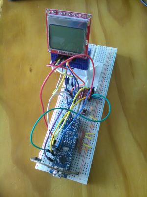
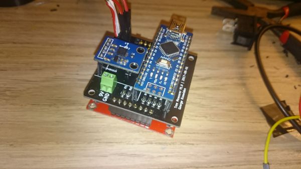
I soldered the PCB, and made many changes to the code. In fact, every single item on the software TODO was completed. It's been a fun day! It turns out that the ADXL pinout was correct, but the pin spacings were not correct on the PCB. I'll have to make sure to update this. The screw terminals from RS fit perfectly in their new footprints. The PCB needs to be updated so that it fits the new standard Nokia 5110 screen. I really liked the hand soldering footprints for the resistors, and the new soldering iron made it a pleasure. I also need to put the whole project into a box with a handle so that I can test it.
Next actions:
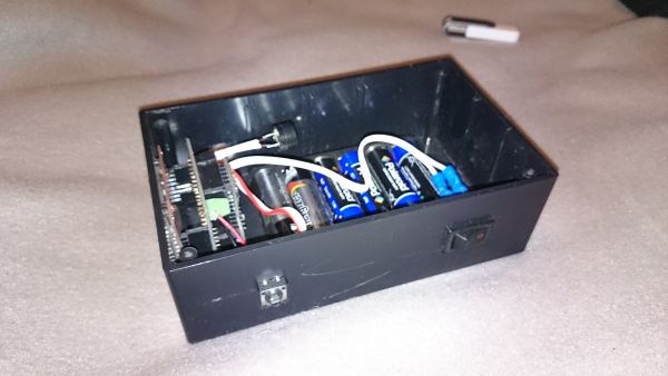
I mounted it in a box and tested against a known height. It measured 4.9 m for a 5.1 m height: I'm pretty sure that an error of 5% or less is acceptable. My requirements stated "accurately measure the height of a tree", I should have been more specific. There is one weird bug at the moment where the displayed realtime angle is a few degrees higher than the actual measured angle, but this is more of a cosmetic problem.
I also updated the code in Github.
Next actions:
I took some measurements today. The main objectives were:
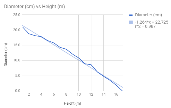
The database measurements were gathered without incident, although the bark on the outside of the tree created some measurement idiosyncracies. It seems that the average diamter has increased from 169.4 to 172.5 mm. So, that's a 3.7% increase in cross sectional area, over a time period of just over 2 months. Actually, a 4.3% increase once the outliers (bark interference) were removed. It's not clear yet exactly what's going on with the tree heights, since the tool is not proven yet.
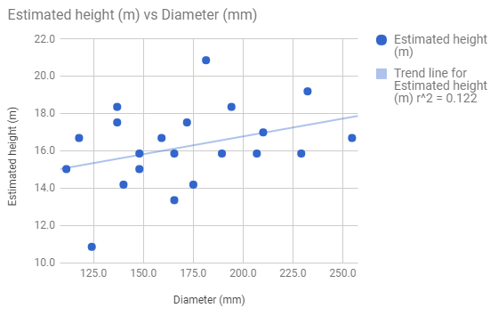
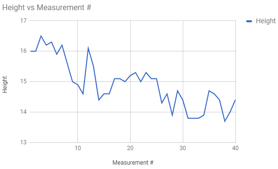
In terms of the accuracy of the Tree Measurer, I did a test where I measured the same tree 40 times, resetting the device after the first 20 measurements. Looking at the graph, I can see a serious amount of measurement drift, which suggests low accuracy. I think this device is more or less useless. I think I can attribute almost all of the error to the accelerometer: the ADC/DAC quantisation error, combined with any supply voltage variation etc. could easily account for this weird behaviour. It definitely isn't a software problem, though improvements can be made here too. So, this needs to be redesigned with a digital accelerometer like an ADXL345. I've got one coming in the mail which should arrive in early November. In the meantime, there is little I can do besides deisgn and order the new PCB. If I reuse the screen/box/buttons, then I can save a few dollars. I might even be able to resolder some stuff. I will need to buy some M2 screws/nuts though.
I also need to check that the ADXL345 is going to be sufficient in terms of accuracy. It seems that the ADXL335 is around 70 LSB/g ('g' for 1 Earth gravity) in the configuration I was using it, whereas the ADXL345 is 256 LSB/g. Therefore, the precision of the ADXL345 is nearly 4 times as great as the ADXL335. If I'm reading the datasheet correctly, the accuracy for the X and Y axes is around +/- 40 mg, and Z is +/- 80 mg. So, that seems to be roughly a 0.5% or 1% typical error, respectively. The Z axis is also particularly sensitive to temperature changes (+/- 4.5 mg/C) though the X and Y are less sensitive (0.8 mg/C). By incorporating a temperature sensor, this could be adjusted for.
Next actions:
If I'm going to do this properly, I feel that I should incorporate a temperature sensor into the project. After a quick scan, it seems that most temperature sensors are only really good to +/- 1 C, and therefore choosing the cheapest one that does this makes sense. The datasheet for the MCP9700 says that I should be able to get 10 mV / C, which means that with a 5 V supply voltage for the Arduino, it should be able to measure 5/1024 ~= 5 mV = 0.5 C per division of it's ADC. This, combined with the calibration explained in the datasheet should bring both the accuracy and resolution down to around +/- 0.5 C. Pretty good for a $0.30 chip! I'm going to buy a bunch, in either the SOT-23 or TO-92 packaging. Tempted to get the TO-92 for the extra price, since it lets me use them on a breadboard. Yeah, it'll be worth the flexibility.
So, I've added in the ADXL345 and MCP7900 to the layout. No other real changes are required to the layout. The PCB could do with incorporation of the speaker onto the board itself, and I might rotate the Nano to make it easier to use in the box. It wouldn't be a bad idea to move a few of the pin connections either.
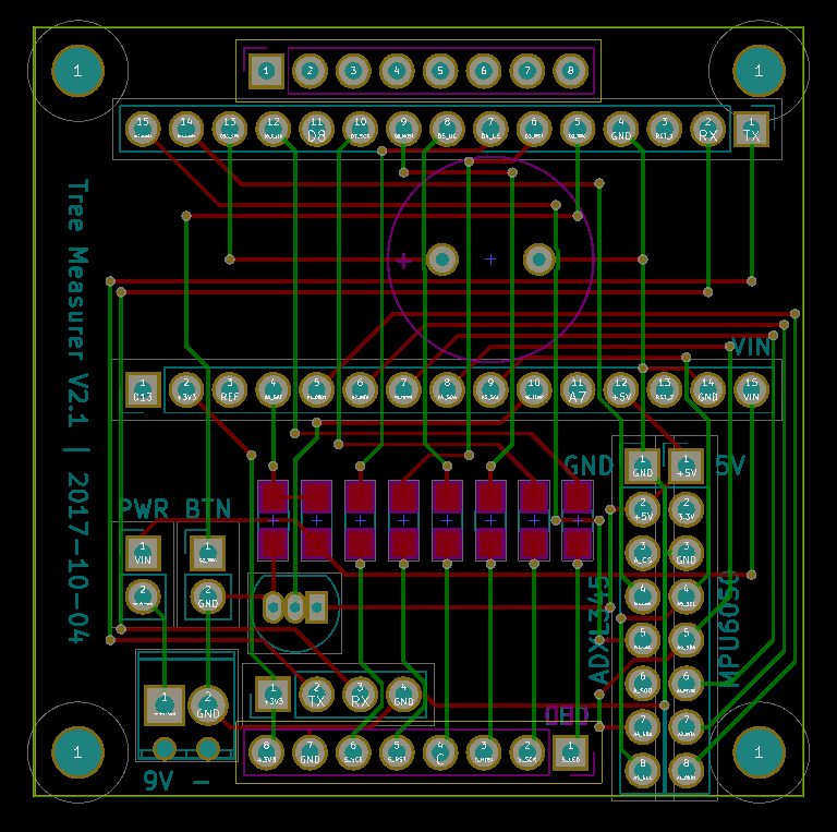
After a chat with a friend, the MPU6050 was chosen as a better choice for an accelerometer/gyro. The breakout board I'm using even has an onboard temperature sensor, so it will be interesting to do some comparisons there.
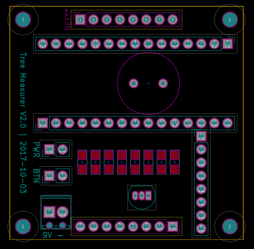
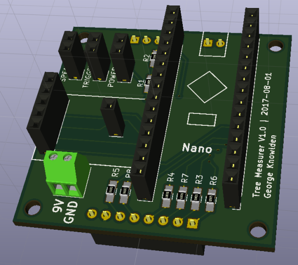
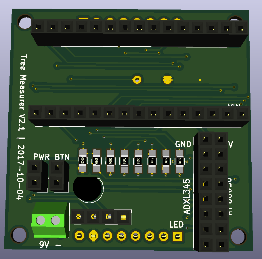
The PCB layout got a lot of changes. Generally, the Nano was reoriented for easier programming, and the speaker was soldered into the board. The resistors were lined up for ease of manufacture. The button/switch connections were moved to a more accessible place.
I also caved and bought those M2 screws and nuts. I'm an absolute sucker for hardware.
I'm starting to wonder if it would be a good idea to build in the possibility of a rangefinding upgrade into this version. The more I think about it, the more sense it makes. I'll add it to the top of the list. The one I'm interested in testing is this "50m Laser Distance Meter Measuring Sensor Range Finder Module Diastimeter F0H3".
Next actions:
I've just realised that I can provide connections to both the ADXL345 and the MPU6050, so I added it back in. Also on I2C for ease of use. I would put in some pull-up resistors, but I think that both the ADXL345 and MPU6050 breakouts are providing them. Alright, now for the range measurements. Some Spanish product detials suggest a serial connection. Weirdly, it needs a 3.3 V supply though. So, I better add breakouts to the RX and TX pins, and also provide a location for a 3.3 V regulator. Actually, I don't think a dedicated supply is needed, I'll just use the Nano's 3.3V supply.
PCB has been routed, and is waiting in the checkout. It occurs to me that I might need a few more female headers.
Next actions:
The board has arived, and been assembled, and tested with the ADXL345: it seems to work! I need to properly calibrate and test it, and also try the MPU6050.
I think that in general, this shows that the idea works.
Next actions:
I was reading the application notes for the ADXL345, and they have totally changed the way I'm thinking about the angle calculation. Apparently, a 2 axis calculation will be fine, though the resolution wuill drop off with rotation through the xz or yz planes. The main advantage of this is increased transparency of the calivration process, and simpler code for my poor little brain.
I think I basically need to calibrate the accelerometer in known g fields, and then use a simple angle offset for the final device to take care of any rotation through the axis of interest. To do this, I'm going to need to be able to place that particular accelerometer in a cube with perpendicular, flat sides, with the accelerometer orthogonal to the cube, and place that cube on a flat, horizontal surface.
A slightly easier way would involve rotating the device until the readings were maximal/minimal in each axis, and using these values for the 2 point calibrations descibed by equations 17 and 18 of AN-1057.pdf. The trick here is to avoid any DC offset in these measurements by not bumping the device, etc, and using a very low pass filter. I may have to ignore the effects of temperature entirely, and simply calibrate at room temperature.
| axis | min | max | offset (calculated) | gain (calculated) |
|---|---|---|---|---|
| x | -264.2 | 276.2 | 6.0 | 270.2 |
| y | -260.6 | 281.5 | 10.45 | 271.05 |
| z | -269.8 | 228.0 | -20.9 | 248.9 |
Then, the average angle error was (1.3 + 1.6 + 1.9 + 2.4) / 4 = 1.8 degrees.
Some initial testing shows that this is probably now bang on! I now need to design a proper test for this at exactly 10 m way from an object of a known height ~ 20 m.
Next actions:
I did my best to calibrate the tree measurer. Over 20 measurements, it was 3.61% lower than the laser measured height of a power pole, with a standard deviation of 0.88%. This can be deemed accurate enough for use at the farm, since human error is likely to be larger than this margin (it is difficult to psition oneself exactly 10 m from the center of a tree).

I think that after cleaning up the code a little, this is ready to go into the field.
Next actions: